此示例展示如何读取模拟引脚0处的模拟输入,将analogRead()中的值转换为电压,并将其输出到Arduino软件(IDE)的串口监视器。
必需的组件
你将需要以下组件:
- 1 × Breadboard 面包板
- 1 × Arduino Uno R3
- 1 × 5k欧姆可变电阻(电位器)
- 2 × 跳线
- 8 × LED(LED条形图显示如下图所示)
程序
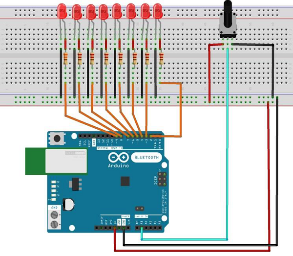
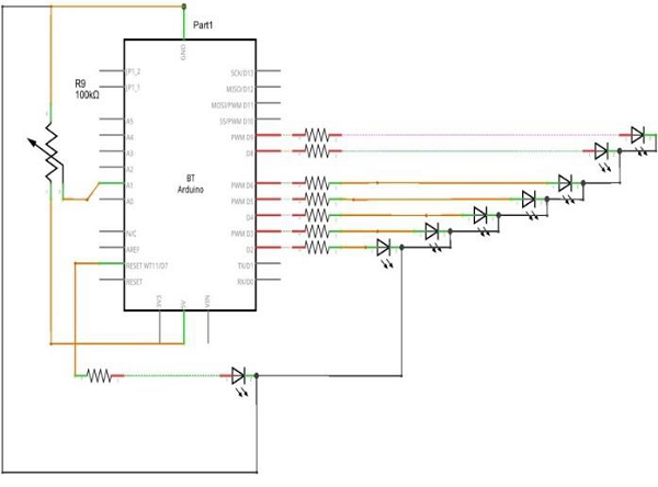
按照电路图连接面包板上的组件,如下图所示。

草图
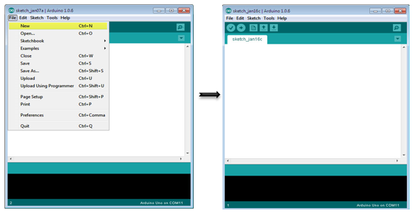
在计算机上打开Arduino IDE软件。使用Arduino语言进行编码控制你的电路。通过单击“New”打开一个新的草图文件。
10段LED条形图
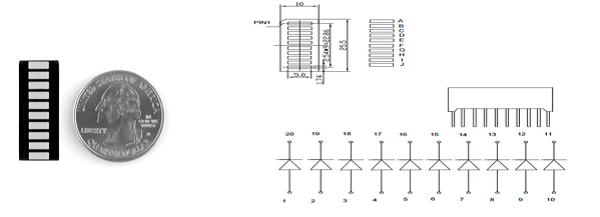
这10段条形图LED有许多用途。紧凑的占用空间,简单的连接,它们易用于原型或成品。实质上,它们是10个独立的蓝色LED,每个都有独立的阳极和阴极连接。
它们也有黄色,红色和绿色。
注意 – 这些条形图上的引脚可能与数据表中列出的内容不同。将设备旋转180度将纠正变化,使得引脚11成为第一引脚。
Arduino代码
/*
   LED bar graph
   Turns on a series of LEDs based on the value of an analog sensor.
   This is a simple way to make a bar graph display.
   Though this graph uses 8LEDs, you can use any number by
      changing the LED count and the pins in the array.
   This method can be used to control any series of digital
      outputs that depends on an analog input.
*/

// these constants wont change:
const int analogPin = A0; // the pin that the potentiometer is attached to
const int ledCount = 8; // the number of LEDs in the bar graph
int ledPins[] = {2, 3, 4, 5, 6, 7, 8, 9}; // an array of pin numbers to which LEDs are attached

void setup() {
   // loop over the pin array and set them all to output:
   for (int thisLed = 0; thisLed < ledCount; thisLed++) {
      pinMode(ledPins[thisLed], OUTPUT);
   }
}

void loop() {
   // read the potentiometer:
   int sensorReading = analogRead(analogPin);
   // map the result to a range from 0 to the number of LEDs:
   int ledLevel = map(sensorReading, 0, 1023, 0, ledCount);
   // loop over the LED array:
   for (int thisLed = 0; thisLed < ledCount; thisLed++) {
      // if the array elements index is less than ledLevel,
      // turn the pin for this element on:
      if (thisLed < ledLevel) {
         digitalWrite(ledPins[thisLed], HIGH);
      }else { // turn off all pins higher than the ledLevel:
         digitalWrite(ledPins[thisLed], LOW);
      }
   }
}
代码说明
草图的工作方式是这样的:首先,你阅读输入。将输入值映射到输出范围,在这种情况下为十个LED。然后,你设置一个 for-loop 以迭代输出。如果系列中的输出数量低于映射的输入范围,则将其打开。如果没有,则将其关闭。
结果
当模拟读数的值增加时,你将看到LED逐个打开,而当读数减少时,LED逐个关闭。
作者:冒牌SEO,如若转载,请注明出处:https://www.web176.com/arduino/16415.html
 支付宝
支付宝  微信
微信